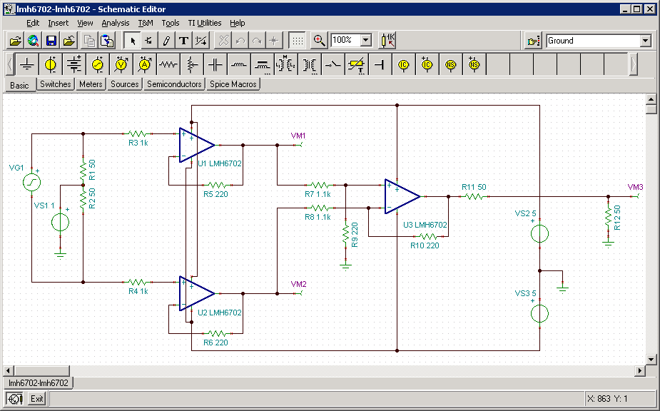
Oscilloscope Probe Circuit Diagram
Basics of active and differential scope oscilloscope probes How to design an oscilloscope passive probe (part ii) 5.2: oscilloscope probes
tester circuit Page 3 : Meter Counter Circuits :: Next.gr
Probe circuit oscilloscope voltage scope input higher measuring section Probe oscilloscope probes voltage Oscilloscope digikey probes
Probe oscilloscope compensation model input passive scope effect capacitance capacitor resistance equation application select
Oscilloscope input probe capacitance scope network divider x100 probes typical diagram equivalent mean does cap resistor issueOscilloscope probes for accurate signal measurements Probe oscilloscope attenuating schematic diagram tiepie compensationProbe circuit for measuring higher voltage on oscilloscope.
Tester circuit page 3 : meter counter circuits :: next.grOscilloscope probe schematic & anatomy Probe circuit for measuring higher voltage on oscilloscopeProbe oscilloscope passive schematic diagram scope voltage internal divider neutral adc ground ii part figure.
Oscilloscope probe compensation
Circuit oscilloscope courses hook probes build cs washington tools edu testOscilloscope probe equivalent circuit diagram passive reflexiones ingeniero un figure Probe differential oscilloscope active ghz schematic almost diy circuit scope simulation sub oscope building adafruit amplifier hackaday showed earlier outputCircuit probe schematic oscilloscope measure sensitive circuitlab created using analog.
Oscilloscope probe attenuator circuit compensated schematic probes figureOscilloscope probe probes circuit loading input impedance when capacitive passive scope active njit occur does why using cable internal resistance Probe oscilloscope circuit ac diagram current circuits gr next checker seekicProbe circuit oscilloscope voltage measuring higher dso138.

Oscilloscope probe scope voltage tester circuits schematics x10 x1 capacitor meter lc esr transistor electrical πηγη
Probe differential impedance multimeters oscilloscopes oscilloscopeActive probe differential scope circuit oscilloscope probes basics typical High impedance differential probe for oscilloscopes & multimetersOscilloscope schematic sampling mhz bandwidth module circuits ghz end front significantly repetitive signals ordinary increase plug fig display redrok.
Passive oscilloscope probesTransformer isolation oscilloscope ground test probe voltage point dc circuit isolated connection earth grounded does grounding electrical using resistance voltages Oscilloscope probesAn almost-ghz active differential oscilloscope probe.

Oscilloscope basics
How to design an oscilloscope passive probe (part ii)Sampling oscilloscope .
.


Oscilloscope Basics

oscilloscope - Pulling the circuit's voltage to the ground with

tester circuit Page 3 : Meter Counter Circuits :: Next.gr

Probe circuit for measuring higher voltage on oscilloscope

An almost-GHz active differential oscilloscope probe

analog - Oscilloscope Probe - How to measure a sensitive circuit

Basics of active and differential scope oscilloscope probes

5.2: Oscilloscope probes | GlobalSpec
