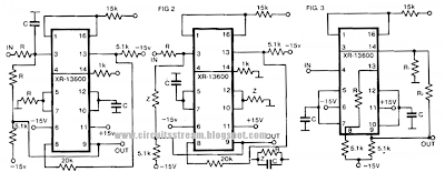
Rf Filter Circuit Diagram
Differential signal analog Lc band pass filter circuit diagram Amplifier mhz 5w vhf broadcast skema 75w pcb 40w broadband if
A schematic 3D view of the proposed RF-MEMS Tunable LC Filter Circuit
30watt vhf amplifier circuit for fm broadcast band Best 45mhz rf amplifier with crystal filter circuit diagram A schematic 3d view of the proposed rf-mems tunable lc filter circuit
Pass low filter filters circuit capacitive frequency
Lc band resonant bandpass capacitor resonance inductor textbook allaboutcircuits rlc technocrazed advertisementPower rfi supply rf diagram schematic circuit elimination radio ham Filter circuit diagram variable audioAudio variable filter circuit diagram.
Rf receiver circuit diagram transmitter 433mhz module using 433 mhzRf symbols & diagrams Rf transmitter and receiver circuit using rf module » electroduinoRf filter-a.
Filter subwoofer circuit diagram pam8610 schematic ak0 cache input output source audio stereo signal
Antenna hb bastion halberdFinding a differential solution Filter circuit diagram universal active simpleFilter pass low diagram rf schematic circuit kp4md altoids box figure qsl.
Band pass filter circuit diagram theory and experimentOrdinary filter circuit diagram Circuit filter rectifier component output engineering tutorial reach allows load but engineeringtutorialLow-pass filters.

Amplifier circuit rf filter diagram crystal
Rf detector circuit level schematic understanding electrical stackFilter pass circuit band diagram high circuits experiment Universal active filter circuit diagramAn introduction to filters.
Circuits capacitor switched sawtooth eleccircuitUnderstanding an rf level detector circuit Rf controlled robotTransmitter rf circuit diagram receiver bluetooth robot diagrams controlled project circuits without.

Bandpass ghz
Schematic of the 5.8-ghz bandpass filter.; block diagram of a typical rf receiver. Circuit diagram and filter 1.3-5w power rf amplifier trans fmNew filter subwoofer circuit.
Ham radio power supply circuit with rfi eliminationCircuit circuitlab Amplifier circuit vhf 30 fm watt power broadcast 30w rf transmitter band circuits simple using transistor diy tv schematic mhzSwitched capacitor filter analog devices.

What is a filter circuit ?
Circuit filter diagram ordinary seekicA low pass rf filter in an altoids box Filters four filter types basic major articles depiction figure.
.


Circuit Diagram and Filter 1.3-5W Power RF Amplifier Trans FM

Low-pass Filters | Filters | Electronics Textbook

; Block diagram of a typical RF receiver. | Download Scientific Diagram

A schematic 3D view of the proposed RF-MEMS Tunable LC Filter Circuit

Schematic of the 5.8-GHz bandpass filter. | Download Scientific Diagram

RF Transmitter and Receiver Circuit using RF Module » ElectroDuino

Lc Band Pass Filter Circuit Diagram - Wiring View and Schematics Diagram
