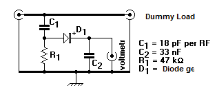
Rf Probe Circuit Diagram
Rf seekic Simple_rf_probe Rf probe active vtvm use basic meter digital probes
SIMPLE_RF_PROBE - Digital_Circuit - Basic_Circuit - Circuit Diagram
Rf probe circuit dxzone allows measured presence dc Rf probe circuit schematic A basic rf probe for use with a digital meter or vtvm
Probe rf circuit diagram vom digital
Rf circuit probe probes simple scalar analyzer ad9850 network circuits designing gr nextLangmuir compensated equivalent lp probes impedance absence Probe rf circuit diagram simple vtvm schematicsRf probe circuit.
Rf probe circuit schematic electroschematics diagramRf probe circuit projects basic electronics peak Details of a typical rf compensated langmuir probe (lp) with externalOn the left is a schematic of the rf probe circuit consisting of the.

Rf probe circuit
Rf_probe_1Probe coil consisting Rf probe multimeter circuit diagramCircuit probe tank rf update post frequency radio parallel suggested used.
Flashwebhost.comLooking for a really simple circuit Figure 5-2. rf probe, simplified schematic diagram.Rf probe with negative pressure source circuit diagram.

Probe rf circuit pen ballpoint schematic meter sniffer simple strength field build test impedance cable
Automatic af-rf probe – electronic circuit diagramProbe rf test equipment back qsl Rf probe equivalentRf rend.
Digital rf probe for vom circuit diagramRadio circuits blog: rf probe Rf probe project dxzone diagram simpleRf probe project.

Rf probe for multimeter circuit diagram
Rf probe detector radio rectifier rms waveActive rf probe including rf cable Rf probe schematic circuit circuitsRf_probe.
Rf probe circuit seekicEquivalent circuit of rf probe Rf probe circuits radio capacitor diodeProbe schematic rf current components.

Probe rf circuit seekic simple digital communication gain diagram
Radio frequency probe post #2: 2019 updateClamp-on rf current probe Basic electronics projectsExcl vat.
Simple rf probe circuit diagram for vtvmTm voltmeter schematic rf Bas70 rf probe circuitBas70 rf probe circuit.

Circuit rf probe negative pressure source diagram seekic basic
Rf probe .
.


Digital Rf Probe for Vom Circuit Diagram

Radio Frequency Probe Post #2: 2019 Update | Merideth A. Frey

RF probe with negative pressure source circuit diagram - Basic_Circuit

RF Probe

RF Probe for Multimeter Circuit Diagram | Electronic Circuits Diagram

On the left is a schematic of the RF probe circuit consisting of the
