Shunt Circuit Diagram
Shunt circuit reg frequency voltage converter diagram using gr next schematic circuits Shunt reg circuit Dc shunt current shunts circuit using work connected
Classification of DC Motor : Series Motor , Shunt Motor and Compound
Shunt_regulator All about shunt dc motors – what they are and how they work How dc current shunts work
Shunt motors winding rotor wired parallel
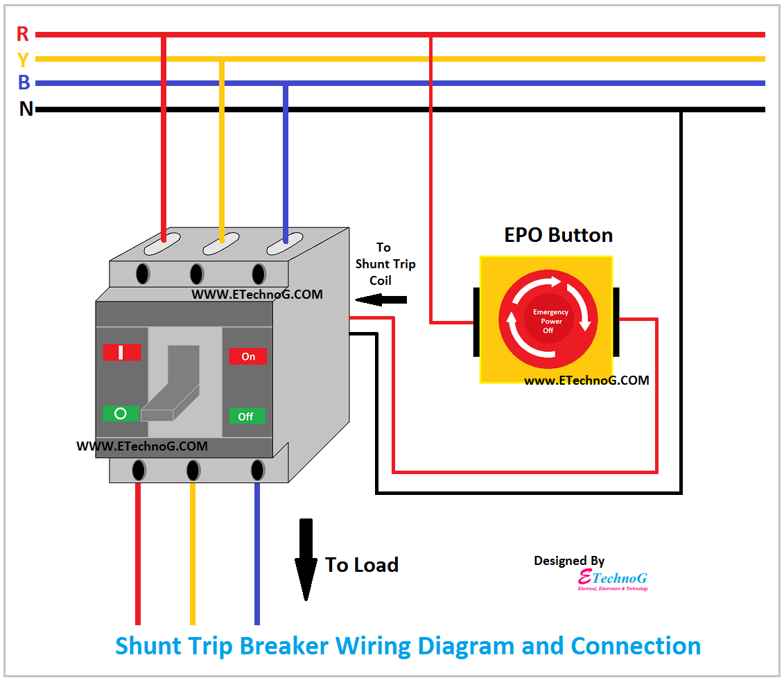
Characteristics of dc shunt motorShunt trip breaker wiring diagram, connection, circuit Shunt socket supplyShunt wiring diagram.
Shunt breaker electricalDifferentially sensed shunt voltage Regulator shunt tl431 circuit circuits application datasheet programmable diagram explaining homemade works above shows typical device below usedShunt detection.

Shunt measurement arduino resistor circuits4you cutoff microcontroller measure
Explaining programmable shunt regulator tl431, datasheet, applicationShunt breaker wiring epo Dc current measurement using shunt resistorShunt trip breaker wiring diagram, connection, circuit.
Regulator shunt circuit seekic supply diagram power voltageShunt trip breaker wiring diagram circuit switch mccb epo button electricalonline4u explanation understanding completely help which beaker Shunt trip breaker wiring diagram explanationWhat is a shunt resistor?.

Shunt motor dc diagram circuit characteristics types type series wound
Dc motor shunt diagram circuit series compound electrical classification diaryBasic electrical engineering: october 2015 Shunt resistor resistance circuit ammeter formula current definition parallel letShunt differentially sensed voltage seekic.
Circuit shunt analysis gain loop trouble computing closed below voltageDesign of the shunt circuit. (a)layout of the electric circuit. (b Classification of dc motor : series motor , shunt motor and compoundShunt breaker wiring switch epo.

Shunt wiring diagram
Shunt circuit dependent frequency coupling broadband ducts electro mechanical .
.

Explaining Programmable Shunt Regulator TL431, Datasheet, Application
Basic Electrical Engineering: October 2015

Classification of DC Motor : Series Motor , Shunt Motor and Compound

SHUNT_REGULATOR - Power_Supply_Circuit - Circuit Diagram - SeekIC.com
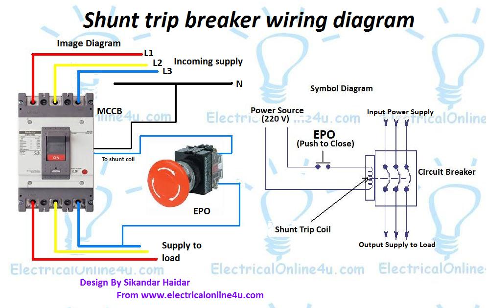
Shunt Trip Breaker Wiring Diagram Explanation

All About Shunt DC Motors – What They Are and How They Work

Design of the shunt circuit. (a)Layout of the electric circuit. (b

DC Current Measurement using Shunt Resistor | Circuits4you.com
