Shunt Voltage Regulator Circuit Diagram
Voltage regulator circuits Transistor shunt voltage regulator Regulator shunt circuit diagram voltage supply seekic zener corp rectifier diode output handbook 1960 less international than used when
Voltage Regulators,Circuits,Types,Working principle, Design, Applications
Regulator voltage shunt figure Voltage regulator shunt diagram block types control regulation definition making element electronics working Shunt regulator circuit tl431 current diagram circuits transistor datasheet application high explaining programmable higher shown parts homemade works
Zener diode voltage regulator
Figure 4-39a.shunt voltage regulator. increase in output voltageShunt regulator voltage zener diode Voltage regulators, different types, working principle, designRegulator shunt.
Regulator voltage diagram block shunt transistorVoltage block regulator shunt diagram regulators transistor discrete Regulator shuntDc voltage regulator circuit – electronics post.

Adjustable shunt regulator – electronic circuit diagram
Constant voltage using shunt regulatorRegulator transistor circuit zener diode feedback electronics electronicspost Figure 4-37.shunt voltage regulatorZener diode regulator voltage circuit diagram do formulas current limiting vz electrical.
Regulator shunt transistor power circuits regulated fig learnabout psu electronicsWhat is a voltage regulator? definition, types and working of voltage Regulator shunt voltage diagram schematic figure referHow shunt regulator tl431 works, datasheet, application.

Circuit diagram of transistor shunt voltage regulator
Regulator voltage transistor shunt circuit diagramShunt regulator voltage constant using Shunt voltage regulatorFigure 4-37.shunt voltage regulator.
Voltage zener regulator transistor shunt regulators circuits principleRegulator shunt tl431 circuit circuits application datasheet programmable diagram explaining homemade works How to make voltage regulator circuitsVoltage regulator shunt circuit circuits regulators.

Regulator shunt voltage transistor circuit diagram shown below electronicspost
Circuit schematic of shunt regulator.Draw block diagram of a shunt voltage regulator and explain the working Regulator circuit shunt voltage seekic ic input parallel 1µf intergrated connection switch every side use twoShunt regulator circuit.
Explaining programmable shunt regulator tl431, datasheet, applicationVoltage regulators regulator circuit diy Shunt_regulator_1Regulator voltage shunt.

Voltage regulators,circuits,types,working principle, design, applications
Dc voltage regulator circuitRegulator voltage shunt schematic figure Block diagram of transistor shunt voltage regulatorRegulated power supplies.
Regulator shuntShunt regulator adjustable diode circuit diagram acts adjust zener voltage via but Figure 4-32.series voltage regulator.


Constant voltage using shunt regulator - Electrical Engineering Stack

Regulated Power Supplies
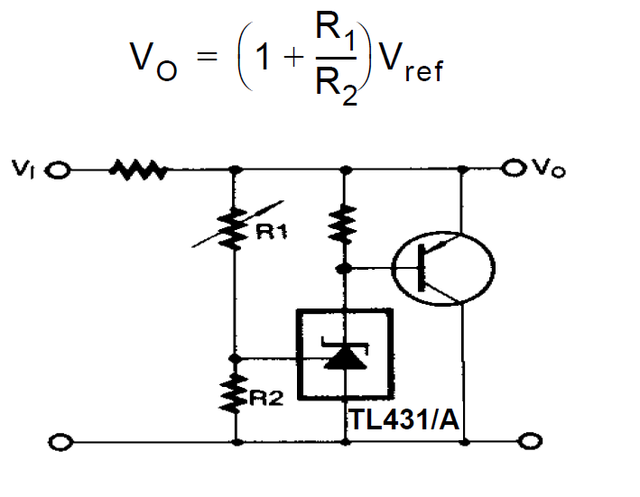
Explaining Programmable Shunt Regulator TL431, Datasheet, Application

Voltage Regulators,Circuits,Types,Working principle, Design, Applications

circuit diagram of transistor shunt voltage regulator - Electronics Coach

Zener Diode Voltage Regulator

How Shunt Regulator TL431 Works, Datasheet, Application | Homemade
